- Email orientflex@orientrubber.com
- WhatsApp / Phone+86 180 3186 9514
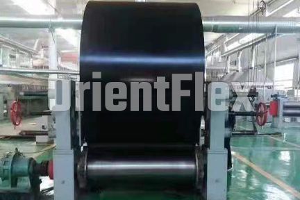
In the material handling business, we often see belt conveyor systems with external speed sensor wheel arrangements to detect and monitor running belt speed.The speed of belt conveyors, drive pulleys... and all other rotating equipment is necessary to monitor the entire system. One of the important speeds is the conveyor belt speed.
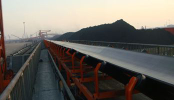
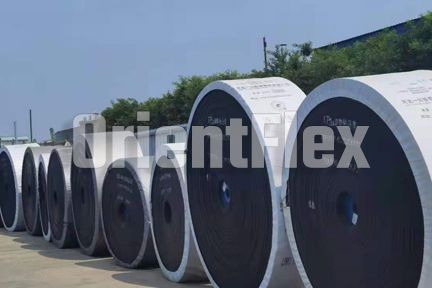
Accurate and reliable measurement of conveyor belt speed is critical in many production and manufacturing facilities to ensure continuous transportation of production materials, work-in-process or finished products. Large conveyor belts are efficient and easy to use, making them particularly effective and often required when transporting heavy bulk materials such as iron ore, coal, fertilizer or grain. In mass production, many manufacturers use multiple conveyor belts, some running at higher speeds and others slower, depending on the nature of the production for a particular step.
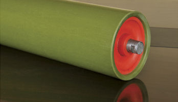
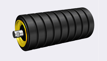
Measure the circumference of the rollers in the conveyor belt
Calculate the revolutions per minute, then multiply these two numbers to determine the belt speed. Manufacturers and grocery stores often use conveyor belts to move products along specific paths. As the drum rotates, objects and materials placed on top of the conveyor belt will move from side to side. The speed at which the conveyor belt moves depends on the size of the drum and its revolutions per minute.
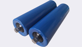
Measure the diameter of the rollers that wrap the conveyor belt
Multiply the diameter of the roller by pi, 3.14159. This calculation yields the circumference of the roller. For each revolution of the drum, the conveyor moves a linear distance equivalent to the circumference of the drum. Pi is a dimensionless factor, which means it doesn't matter if you use inches, centimeters, or any other unit of measure.
Measure the revolutions per minute of the drum
Count how many revolutions the wheel makes in one minute. Multiply the RPM by the circumference of the drum. This calculation provides the linear distance a point on the conveyor belt travels in one minute.
Calculate the distance in one hour
For example, a 2-inch diameter roller would have a circumference of 2 x 3.14159 or 6.28 inches. Multiply that number by the number of revolutions, in this case 10, for a total of 62.8 inches of travel per minute. Multiply by 60 to get the total inches traveled per hour, or 3,768. Next, divide by 12 to get 314 feet, then divide by 5,280 to convert to miles per hour, 12 inches = 1 foot, 5,280 feet = 1 mile. In this example, the conveyor is running at approximately 0.05947 MPH.
Optical method
The goal is to replace current shaft encoders in conveyor setups with a non-contact and cost-effective optoelectronic speed measurement device. Existing conveyors use shaft encoders to measure the speed of the conveyor. The main disadvantage of these encoders is that they are in contact with the conveyor belt. This reduces the life of the belt because the contact of the encoder wheel can cause the belt to wear. The IR transmitter and receiver effectively measure drum speed when placed against a rotating disc containing alternating black and white patterns. The alternative black and white color pattern was chosen because IR light has the property of being absorbed by black areas and totally reflected by white surfaces. The idea to use IR LEDs instead of encoders for speed measurement is suggested to be a non-contact and cost-effective solution. Placing a suitable lens in front of the IR transmitter and receiver will increase the measurement distance without compromising the reliability of the conveyor belt speed output.
Measuring Conveyor Belt Speed Using Encoders
Indirect monitoring of the motor shaft using an encoder
Indirect measurement methods include monitoring the motor shaft that drives the conveyor belt. The encoder should be mounted directly on the motor shaft. It will output a pulse stream (for an incremental encoder) or digital word (for an absolute encoder) corresponding to the displacement of the motor shaft.
To convert from the encoder output, it is necessary to physically measure the amount of travel introduced by one revolution of the motor. For a constant travel L, the drive can calculate the velocity in feet per second as s=L/PPR*fp*60, where fp is the pulse frequency in Hertz.
The disadvantage of this approach is that it does not take into account the mechanical tilt that may be introduced by couplings, gearboxes, belt slippage, etc. This also brings up an important point: the mechanical properties of the conveyor belt and the speed resolution of the motor are the limiting factors for keeping the same speed as the conveyor belt. All the encoder can do is report. The resolution needs to be high enough so that the encoder can accurately report the change in position converted to velocity. Specifying an encoder with a resolution higher than that will not improve system performance and may even result in erroneous readings.
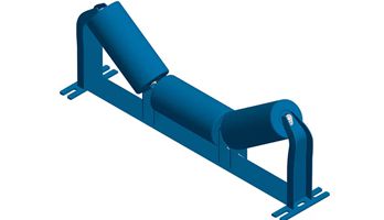
Indirect measurement of roller shafts using encoders
Depending on access to the motor, it may be easier to mount the encoder on the roller shaft.
In this case, the drive converts the encoder output to linear velocity s in feet per second, RPM=fp/R*60, where fp is the pulse frequency in Hertz and R is the number of pulses per revolution resolution in units. Linear speed s = 60RPM*πD/12, where D is the diameter of the roller in inches.
While more accurate than a motor-mounted encoder, this method is still subject to mechanical errors introduced by belt slippage, etc.
Direct measurement with encoder measuring wheel
A third way to monitor the speed of the conveyor belt is to attach an encoder to the encoder measuring wheel. If the belt itself is jammed with product, it will ride on the surface of the belt or one of the rollers. Typically, these wheels are 1 foot in circumference, so it's easy to convert RPM to linear speed in feet per minute.
It's important to remember that driven wheels are mechanical components that reduce accuracy. Sources of error include misalignment and slippage between the wheel and the surface being measured. Applying preload helps prevent slippage, but increases bearing wear. Finally, the driven wheel itself will wear out, especially if it is misaligned. To address this, some encoder measuring wheels have double O-rings on the circumference that can be replaced if necessary, extending the life of the wheel itself. Remember that the driven wheel, not the encoder performance, is the limiting source of error.
Synchronize multiple conveyors with encoders
Synchronizing the speed of one conveyor belt with another requires multiple encoders and a master-slave architecture. As mentioned above, the motor has an encoder mounted on the shaft. The slave conveyor has an encoder mounted on a shaft that originates from a set of rollers on the auxiliary conveyor. Both encoders are connected back to the controller.
The component on the slave controller is purely a feedback system. With this input, the controller can monitor any speed difference between the main and auxiliary belts. Any time the difference exceeds the tolerance, the controller can command the drive to accelerate the motor until the speed of the primary belt matches the speed of the secondary belt.
Was this article useful to you?
We are a leading North China owned and operated conveyor specialist with over 20 years of experience in the industry.
We specialise in the design, manufacture and supply of quality conveyor equipment, components and related services.
If you have any questions, please contact us in time, we can provide you with the most professional knowledge.
You can contact or visit us in our office from Monday to Friday from 8:00 - 18:00